Physical Controllers
Most of these sensors are already available as a EGC kit!
This means that you get the full kit with all the components and just need to solder them to the board. The code used in the example is also provided. For more information - please inquire with Georg.
INPUT
Microphone Sensor
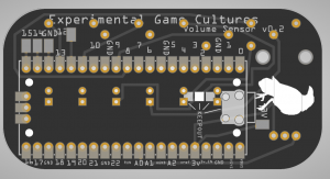
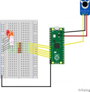
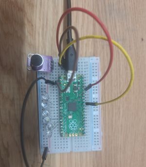
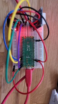
Using a Raspberry Pi Pico with Micropython - Takes a Microphone input and then outputs a gradient on LEDs. This could be of course also be used for a sound sensing controller - move the player only when you make a sound or so.
The wiring:
On a breadboard:
Infrared Sender/Receiver
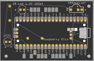
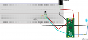
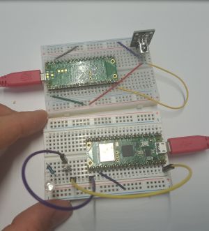
Using an IR Receiver Module & Infrared LED, works pretty easily - with the right library.
Some things to watch out for - the Infrared LED requires a lot of current (mA), the Raspberry Pico as well as the Arduino can't supply that directly. That's why we use a transistor as a switch to turn on/off the LED - this way we can get the full range and power for the LED.
You will need to upload the ir_tx and ir_rx folder to the Raspberry Pico beforehand. Works like a typical TV remote, can send small packets of data (like numbers or hex codes).
The code for the Raspberry Pico and library that needs to be uploaded to the Pico here: File:IrSenderReceiverDoc.zip
Pin 16 - IR Receiver, Pin 17 IR Sender (for our Kit)
Hand holding sensor
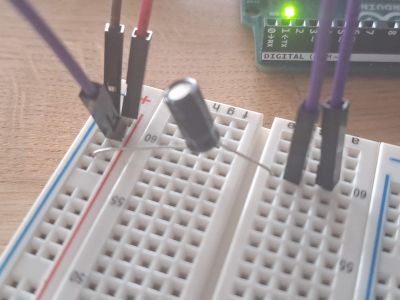
Measure the voltage - could be a chain of humans that hold hands, Arduino measure the voltage and smoothes it out with a capacitor. The LED is just to show the difference in voltage:
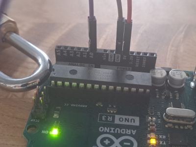
The Arduino connects to 5Volts, Ground and Analog 0
The Breadboard, purple wires are for holding in your hands. Capacitor to smooth out the voltage.
The code
File:Touch.zip
RFID Tag Reader
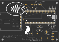
Can be used to read RFID Cards/ or write to them. Uses a ~3 Dollar RFID Reader (RC522) Made to work using Circuitpython and a library. Available as a kit (with extra Neopixel and Beeper for convenience).
The Code: File:Rfid Raspberry.zip
New things found out (21.03.24) - This PN532 Library works pretty well. You just have to make sure you are using the UART pins on the Raspberry Pico. This way you hould be able to connected at least 2 UART devices. https://github.com/insighio/micropython-pn532-uart/tree/main
Crowtronica
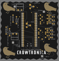
Can use croco clamps to connect to metal, plants, fruit, etc. Measures simple button presses basically. Can output keyboard button presses - use this in conjunction with Unity or an online piano tool to play sounds. The code provided gives basic functionality, you can press on the metal crows in the front to trigger keyboard presses. With the latest code (25.10.23) you get three leds per pad - depending on strength of the press you get different values.
The Code: File:Crowtronica.zip
Joystick & Button Controller
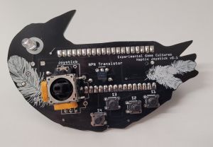
A custom controller with Joystick and buttons. Acts like a keyboard/mouse on your PC.
The Joystick moves the mouse and the buttons can be assigned to keyboard letters. This way you don't need to worry about the mapping in Unity or other projects. It has a motor on the back that can produce haptic feedback. May need to be refitted for different Joysticks.
The Code: File:Joystick.zip
Gyroscope Sensor
To be added - code already here for later reference. File:Gyroscope.zip
OUTPUT
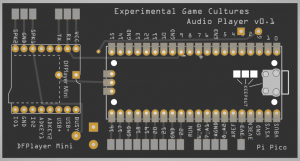
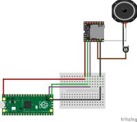
Musicplayer with DFPlayer Mini
A simple module that allows to connect a SD card with mp3/wav files and play them via a small speaker.
Uses the 5 Volt USB Input that feeds the Raspberry Pico (3.3V) in order to get a louder sound.
For more volume, a dedicated amplifier and speaker would be required.
The Code: File:DFPlayerRaspberryPico.zip
SD Card Reader
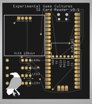
Enables you to write/read to an SD Card. This particular SD Card adapter needs 5V, so we take this from the VBUS of the Raspberry Pico. Script to access storage can be found on the zip file beneath. Formatting the SD Card to FAT32 using the Tuxera SD Card Formatter, although your operating system may have a built in solution.
This particular diagram & kit have an extra OLED screen and LEDs. These are optional but likely helpful to visualize what is going on and what the contents of the SD card are.
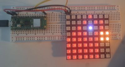
Display with 8x8 LED Neopixel Matrix
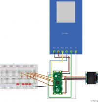
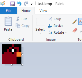
This is using an affordable Neopixel Square for around 8 Euros. (8x8 Matrix mit 64 WS2812 5050 RGB LEDs) The great thing is that we can actually load in image files to this using a simple library.
This is the simple code to use - the main.py script opens the image on the Raspberry and sends it to Pin 16 (where the Data Pin of the Matrix is connected). File:NeopixelMatrixEGC.zip
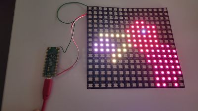
It gets trickier with a 16x16 Matrix - this were just strips of 16 leds connected to each other, the indeces were arranged like a long snake - therefore in the code some rearranging was necessary.
File:Neopixel16x16.zip
Stepper Motor
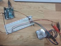
Using a A4988 Stepper Motor Driver, Arduino and a Stepper Motor from StepperOnline ( Nema 17 Bipolar 42Ncm 1.5A ). Setup the Driver as in this diagram File:POLOLU-2128.pdf, using this video tutorial: https://www.youtube.com/watch?v=psI3aN0A-OA
Be sure to use a capacitor to avoid electricity to leak back into the Arduino and make sure to set the current limit on the Driver as described in the stepper driver document. For me it was 0.6v as I wanted a maximum of 1.5 A of current through the Stepper.
Arduino code was here: File:StepperCode.zip
Multi Transistor
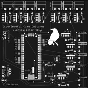
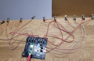
Used to turn off/on up to 12 devices. These could be things that require a larger amount of current to work (such as oldschool bycicle lightbulbs).
We use MOSFETs for this, which are essentially just transistors (can be used as electronic switches). You can also lessen voltage using a transistor and PWM (see script attached). So you could have a 5V input (from USB Power which is a pin on the Raspberry Pico) and then reduce it down to 3v using this.
Additionally, this board has the capabilities to have an IR Receiver and IR Emitter. So you could use an IR remote to control these devices too.
COMMUNICATIONS
ESP 32 + ESP Now
Best strategy - about 8.- each. Follow this tutorial for detailed explanation. Long distance and relatively easy to use. Uses Esp Now Protocol.
https://www.youtube.com/watch?v=bEKjCDDUPaU
Short explanation - you need to assign MAC Adress of receiver ESP now in this example. (tested) File:Esp32-NOW-example.zip
Tips: You may need to install drivers for CH341 chip. In Arduino IDE you need to install the ESP32 Board (espressif). Also make sure you are using the right port (plug into the board itself with USB-C). Set the Baud Rate correctly and you may need to restart your PC if your ports don't work. Also you may need to hold the Boot Button before it uploads, otherwise you get an error during upload. I used the ESP32 Dev Module Firmware for my ESP32 WROOM-32.
Raspberry Pico W To Raspberry Pico W
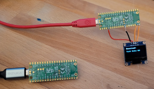
Unfortunately not very reliable.. (~14 EUR) One Pico acts as a Server, one as a client, they communicate wirelessly this way. In the code I made, I used a OLED Display although that could be omitted.
The scripts are here (put one on host pico and one on client, host has the screen)
TIP: Make sure if the Wifi connection doesnt work that you switch to another PC or don't have them both on the same PC. This could interfere!
433 MhZ Transmitter
For short distances, cheap and easy to use. Quite unreliable, can be subject to noise. May require additional power supply or filtering of power line noise.
https://funduino.de/nr-03-433mhz-funkverbindung https://www.instructables.com/Super-Simple-Raspberry-Pi-433MHz-Home-Automation/
One Wire
Just needs one wire + vcc + gnd to communicate. Maybe a good idea?
https://www.elektronik-kompendium.de/sites/raspberry-pi/2703071.htm
Reading Serial Data in Unity
In order to read data from Arduino to Unity, you can simply print out text to the Serial port. Then receive this in Unity with this script:
Important that the Serial Monitor is not open when trying to read. May require plugging in/out the USB sometimes. Also, you need to set the correct Port (COM + Number).
NRF24L01
Did not work.. https://coffeebreakpoint.com/micropython/how-to-connect-a-nrf24l01-transceiver-to-your-raspberry-pi-pico/
Heltec Lora 32 V3
Quite overpowered for simple things, but can connect to wifi and use and charge a battery. Low power consumption, has OLED screen. Simple transfer of data seemed to be working very well. 30 Euro per device.
The installation needs drivers to be installed and in the Arduino IDE to add the boards. https://docs.heltec.org/general/establish_serial_connection.html#for-windows
Here are simple tested custom files for Arduino (receiver and sender). File:HeltecWifiLora32V3.zip
OTHER INFO
RASPBERRY PI AUTOSTART SCRIPTS
This is the best way to do it (in my experience):
Make a shell (.sh) script that enters virtual env (optional) and then runs the python:
#!/bin/bash
source /path/to/your/venv/bin/activate
python /path/to/your/script.py
Make sure the .sh Script is set to be executable and test it. If that works then:
crontab -e
and add this:
@reboot /home/pi/start_my_script_forever.sh
This will launch the script even without having to login.
SEEDUINO XIAO
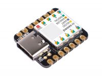
A super small Arduino/Micropython device. About 15 Euros.
Connecting it to Arduino IDE: https://wiki.seeedstudio.com/Seeed_Arduino_Boards/
Unfortunately did not work the first time I used it, may just have been a faulty device..
RTC Clock & 4 Digit Display
The RTC Clock is a DS3132 Module. It seemed to work with CircuitPython and their libraries. The 4 Digit Display uses on Data In Pin and Clock Pin. In the zip file the main code happens on the code.py file, where we set the datetime once, when connected to Thonny, and then display it on the screen.
Deep Sleep with ESP 32
Deep sleep current is way lower than on the RPI Pico (15 μA (0.015 mA)), see this example for a sensor that sends data every 10 minutes: Using ESP NOW and sending data every 10 minutes using a 6000mAh battery: (~1 year)
Deep Sleep with Raspberry Pi Pico
Custom Firmware reduces power consumption to ~2mA, which is excellent for battery powered projects that need long durations where they don't do anything. https://ghubcoder.github.io/posts/deep-sleeping-the-pico-micropython/#release
